Volume & Issue: Volume 2, Issue 3, Summer 2026 
Number of Articles: 6

Torch Set for Gas and Liquid Fuel, Burner Assembly for Fuel Gas & Liquid Fuels

Pages 175-191

https://doi.org/10.5281/zenodo.21472981

Andi Johnson

Abstract The two combustion chambers are located vertically around the turbine and are connected to the turbine housing by side flanges. This type of design makes it possible to keep the inlet air from the compressor to the combustion chamber and from the combustion chamber to the turbine in one direction and causes the least relative pressure drop and relative velocity. Compressed air from the compressor entering the combustion chamber cools the outer shell of the hot gas. In addition, the symmetrical inlet and dual variable airflow results in a symmetrical temperature distribution with minimal pressure change in front of the first row of rotating vanes. Each combustion chamber consists of 8 burners (BURNER) designed for both gas and diesel fuel. Fuel burners operate in accordance with the law of reverse flow. This arrangement of the combustion chamber creates a great flexibility in the dimensions as well as the shape of the combustion system and provides a good possibility for inspection as well as the possibility of easy assembly and disassembly. Combined burners 1 cause diffusion as well as premixing of the flame and produce nitrous oxide and low carbon monoxide without spraying water and steam injection. However, a gas turbine engine can use a water or steam injection system to reduce pollution.

Description of Utility System in Petrochemical Company (Gas Power System)

Pages 192-204

https://doi.org/10.5281/zenodo.21473013

Andi Johnson

Abstract KKS identification codes used to identify various components in the P&I diagram, equipment list, electrical load list, instrumentation list, function diagrams, terminal diagrams, system descriptions, and other documents. In this regard, the specification of power plant units not recounted in general. In addition, as a simple rule, the 4 digits of the equipment key (for example "-S01") are not listed in P&ID. Most valves, precision measuring instruments, etc. have a NAME PLATE installed on which the complete KKS code of the instrument inserted, which also includes the unit number of the power plant. The KKS technical issues in question fully recounted to determine which equipment discussed. For example, the phrase "solenoid valve" MBA41AA010A should be used instead of the phrase "solenoid valve" operating BLOW OFF 1.2, 1.1. KKS coding used to order spare parts. The uniaxial arrangement of the turbine allows the compressor to operate directly and independently of the generator. Combustion of gas or liquid fuel done in two symmetrical combustion chambers with several burners located on both sides of the turbine. Each combustion chamber has 8 burners. Air enters the compressor through the suction channel and through filters and mufflers. In the compressor, the air pressure increases by almost 11 times. Compressed air directed to the burners (above each combustion chamber) and burned in the combustion chambers. Hot gases burned and converted into mechanical power through a turbine. The generator connected to the turbine compressor through the shaft. The electrical power generated by the generator delivered to the transformer through the generator terminals. Exhaust gases reach atmospheric pressure at an approximate temperature of 545 C through an axial diffuser. Exhaust gas enters the open air through a vertical exhaust.

Computational Modeling and Simulation in Corrosion Research: From Atomic Scale to Lifetime Prediction

Pages 205-219

https://doi.org/10.5281/zenodo.21703112

Masood Amiri Koshkeki

Abstract Computational modeling and simulation have emerged as indispensable tools for understanding corrosion phenomena across multiple length and time scales, bridging the gap between atomistic mechanisms and component-level lifetime prediction . This comprehensive review systematically examines the multiscale computational framework for corrosion research, from electronic structure calculations to continuum-scale predictive models. Density functional theory (DFT) provides quantum-level insights into corrosion inhibitor adsorption, with frontier molecular orbital analysis revealing that a lower energy gap (ΔE = ELUMO - EHOMO) correlates with enhanced inhibition efficiency through increased molecular reactivity . Reactive molecular dynamics (ReaxFF) enables tracking of chemical reactions, bond formation and breaking during initial corrosion stages, though time scales remain considerably shorter than realistic corrosion phenomena . Multiscale approaches integrating atomistic insights with finite element method have emerged, preserving grain boundary crystallography while enabling realistic large-scale simulations of corrosion-induced intergranular strain . Phase-field modeling has become a powerful mesoscale tool for simulating autonomous evolution of corrosion pits, capturing the complex interactions between electrochemical processes and mechanical deformation . Machine learning applications have revolutionized lifetime prediction, with hybrid models achieving R² > 0.99 for corrosion rate forecasting and service life prediction . The review concludes that next-generation corrosion modeling requires integrated frameworks combining physics-based mechanistic understanding with data-driven approaches.

Corrosion of Reinforced Concrete Structures: Causes, Monitoring, and Durability Enhancement Strategies

Pages 220-233

https://doi.org/10.5281/zenodo.21792561

Martin Zbuzant

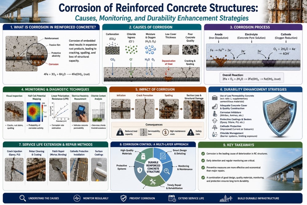
Abstract Corrosion of steel reinforcement in concrete structures is one of the most critical durability challenges facing global infrastructure, with annual economic losses estimated at approximately US$2.5 trillion, accounting for 3.4% of global GDP . This comprehensive review systematically examines the causes, monitoring technologies, and durability enhancement strategies for reinforcement corrosion in concrete structures. The electrochemical mechanism of corrosion involves anodic dissolution of iron (Fe → Fe²⁺ + 2e⁻) coupled with cathodic oxygen reduction (O₂ + 2H₂O + 4e⁻ → 4OH⁻), with rust formation and its 2-6× volumetric expansion relative to steel inducing tensile stresses exceeding concrete's tensile strength . Two primary depassivation mechanisms govern corrosion initiation: chloride-induced pitting corrosion, where chloride ions disrupt the passive γ-Fe₂O₃ layer, and carbonation-driven pH reduction compromising protective film stability . Monitoring technologies have evolved from conventional half-cell potential and linear polarization resistance methods to advanced techniques including electrochemical impedance spectroscopy (EIS), distributed fiber optic sensing, and AI-driven predictive models achieving >98% detection accuracy . Mitigation strategies encompass electrochemical methods (cathodic protection, chloride extraction, realkalization), corrosion inhibitors with demonstrated ~45% weight loss reduction, and emerging polymer-modified concretes reducing chloride penetration by 30-50% while extending service life by 2-3 times . The review concludes that effective corrosion management requires integrated approaches combining mechanistic understanding, advanced monitoring, and sustainable material solutions.

Nanotechnology-Based Coatings for Corrosion Protection: Synthesis, Performance, and Long-Term Stability

Pages 234-248

https://doi.org/10.5281/zenodo.21792727

Martin Zbuzant

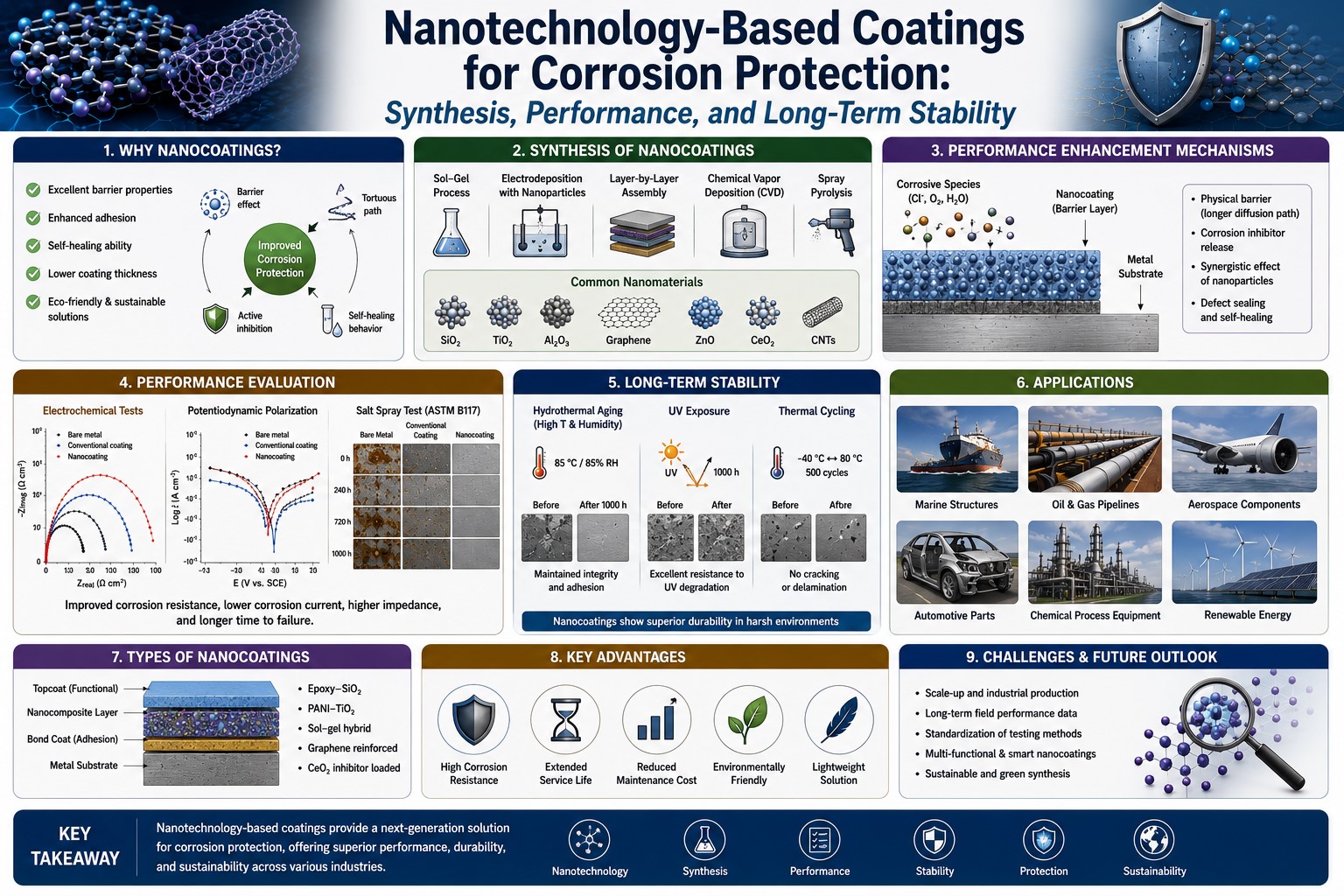
Abstract Nanotechnology-based coatings have emerged as transformative solutions for corrosion protection, addressing the fundamental limitations of conventional barrier coatings through multifunctional design and active protection mechanisms. This comprehensive review systematically examines the synthesis, performance, and long-term stability of advanced nanocomposite coatings for corrosion protection. Key material systems include intrinsically conductive polymers, 2D nanomaterials (graphene, graphene oxide), inorganic nanoparticles (CeO₂, SiO₂, TiO₂, ZnO), and stimuli-responsive nanocontainers. Electrochemical impedance spectroscopy (EIS) results demonstrate that H-CeO₂@GO/epoxy composite coatings maintain high impedance values of 10^9.45 Ω·cm² after 60 days of immersion in 3.5 wt% NaCl solution, while HQZn-PA nanocomposite coatings achieve an impedance modulus of 1.03 × 10^10 Ω·cm² after 40 days with a self-healing efficiency of 99.28% . Self-healing coatings incorporating corrosion inhibitor-loaded nanocontainers enable autonomous repair of coating damage through coordination-controlled release mechanisms triggered by pH, ions, or redox potential changes . Graphene-based coatings provide exceptional barrier properties through their 2D lamellar structure, with incorporation of 5 wt% graphene reducing corrosion rates from 3.4 × 10⁻² to 5.0 × 10⁻⁵ mmpy . Challenges persist in long-term stability under harsh service conditions, dispersion uniformity, scalability, and environmental sustainability.

Blue Hydrogen vs. Green Hydrogen: A Techno-Economic and Environmental Showdown in Heavy Industry Decarbonization

Pages 249-263

https://doi.org/10.5281/zenodo.21892173

Sami Hussun

Abstract The global imperative to decarbonize hard-to-abate (HTA) industrial sectors—including steel, chemicals, and refining—has positioned hydrogen as a cornerstone of the low-carbon transition. Two primary clean hydrogen pathways have emerged: green hydrogen, produced via renewable-powered electrolysis, and blue hydrogen, derived from natural gas with carbon capture and storage (CCS). While both offer substantial emissions reductions compared to conventional fossil-based hydrogen, they entail fundamentally different techno-economic profiles, environmental footprints, and scalability trajectories. This study presents a comprehensive comparative analysis of blue and green hydrogen pathways across key industrial applications, integrating techno-economic assessment (TEA), life-cycle environmental evaluation, and scenario-based cost projections. The findings reveal that green hydrogen exhibits superior long-term economic performance, with costs projected to reach $2.00–3.50/kg by 2030, driven by rapid electrolyzer cost reductions and declining renewable electricity prices. However, blue hydrogen maintains a near-term cost advantage at $1.50–2.50/kg, though this is contingent upon high CCS capture rates (93–97%) and low upstream methane leakage. Critically, the climate benefits of blue hydrogen are significantly undermined by methane leakage rates observed in major gas-producing basins (2.8–3.1%), resulting in lifecycle emissions of 3.5–5.5 kg CO₂e/kg H₂ on a 20-year GWP basis . The green hydrogen-dominant scenario demonstrates superior mitigation economics, saving $115.5 billion compared to blue-dominant pathways while achieving comparable decarbonization outcomes . These results underscore the need for nuanced, sector-specific policy frameworks that account for regional resource endowments, infrastructure readiness, and long-term cost trajectories.